

How Reverse Engineering Enables True Drop-In Replacement Pumps
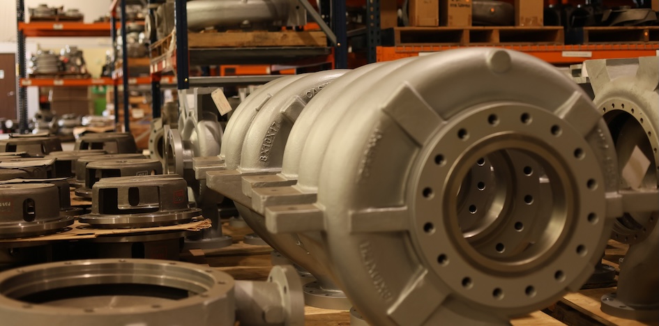
Replacing an existing process pump is not always as simple as selecting another model with a similar performance curve. The new pump may also need to connect to existing piping, align with the driver, fit the foundation and operate across the required conditions. Pump reverse engineering brings those physical and hydraulic requirements together in one design.
What Makes a Pump a True Drop-In Replacement?
A true drop-in replacement pump is engineered to match the existing installation’s defined interface points and minimize changes to the surrounding infrastructure. That means matching more than the pump’s general size.
The engineering team must account for external interface points such as:
- Suction and discharge nozzle locations
- Flange sizes, ratings and orientations
- Shaft height and position
- Coupling and driver alignment
- Baseplate and mounting locations
- Overall pump dimensions
- Existing piping and foundation constraints
Even a small dimensional difference can create field problems. Piping may need to be cut and rerouted, the foundation may require modification or the driver may need to be repositioned. That work adds time and uncertainty to an outage.
Accurately mapping the installed pump gives the replacement design a defined physical envelope.
How Engineers Reverse Engineer a Pump
The process starts with the existing equipment. The pump may be cleaned and disassembled so the casing, impellers and internal passages can be inspected and documented.
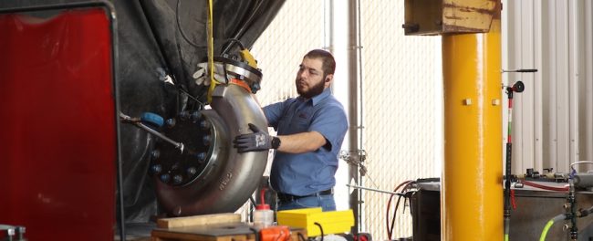
Three-dimensional scanning captures points across the pump to document its surfaces, openings and connection locations. Those points form a digital point cloud that engineers use to create a 3D model of the existing geometry.
This step establishes where the replacement pump must connect to the current system. It does not mean that every internal component should be copied exactly.
Available drawings and performance records do not always agree with the pump’s actual hydraulic geometry. Engineers must compare the physical equipment, available documentation and required operating conditions before developing the replacement design.
Matching the Hydraulics to the Required Performance
A pump can fit perfectly and still fail to meet the application’s needs. That is why dimensional mapping and hydraulic engineering must be treated as separate but connected parts of the project.
The process begins with the required operating data. Engineers review flow, head, speed, fluid properties, pressure requirements and the expected operating range. They then develop the impeller, volute, crossover and other hydraulic passages needed to meet those conditions.
For a multistage pump, this can involve several different hydraulic sections. A first-stage impeller may have a different geometry from later stages. Long and short crossovers may also require individual analysis. Vane counts sometimes need to be adjusted to address pulsation or acoustic vibration concerns.
Computational fluid dynamics, or CFD, allows the engineering team to evaluate flow through each section before manufacturing begins. A multistage design may be divided into several models, with each model analyzed at multiple operating points. If the results do not meet the target curve, the geometry is revised and run again.
A dimensional copy may fit the existing space, but it does not confirm that the pump will meet the required operating conditions. The goal is not to reproduce every feature of the old pump. It is to fit the existing installation and provide verified performance for the application.
Integrating Hydraulic and Mechanical Design
After the hydraulic passages are developed, the pump still needs to become a manufacturable piece of equipment. Mechanical engineers build the casing and internal components around the hydraulic design while accounting for:
- Working pressure and hydrotest pressure
- Flange ratings
- Corrosion allowance
- Structural integrity
- Material selection
- Casting requirements
- Machining access
- Assembly and maintenance
This often requires some back-and-forth between hydraulic and mechanical design. A passage that performs well in a fluid model may interfere with a mechanical component or be difficult to cast, machine or assemble. The design has to satisfy both sets of requirements.
Patterns and core boxes are then developed for the cast components. Allowances must be made for metal shrinkage, machining stock, draft and foundry processes. After casting, the parts move through machining, inspection, hydrotesting and assembly.
Validation Before the Pump Reaches the Site
A drop-in design should not rely on dimensions and computer models alone. The finished pump must be tested to confirm that the manufactured equipment performs as intended.
During final validation, hydrotesting checks the pressure-containing components for leakage, while performance testing confirms flow and head across the specified operating conditions. These tests may follow procedures established in ANSI/HI 14.6.
If testing identifies a performance issue, the hydraulic passages may require further evaluation and correction before shipment.
A Practical Option for Retrofit Projects
Reverse-engineered pumps are especially useful when the existing model is obsolete, replacement parts are difficult to obtain or the original supplier is no longer the preferred source. They can also support pipeline expansions and facility upgrades that need to maintain interchangeability across an installed pump base.
Need a Reverse-Engineered Drop-In Replacement Pump?
PumpWorks can design a replacement around your existing infrastructure and required operating conditions. Contact PumpWorks to discuss your pump, application and installation requirements.