Understanding Centrifugal Pump & Motor Torque-Speed Curve

The motor used to power a centrifugal pump needs to be able to produce enough torque to start the pump and bring it to an optimal operating speed. If a motor lacks enough torque to operate a pump, the pump may not start or may only operate at a reduced speed. The centrifugal pump suppliers at PumpWorks will guide you through the pump motor selection process.
Torque vs. Speed Curve for Centrifugal Pumps
A pump’s torque-speed curve is used to determine the appropriate motor to match with it. A pump’s torque-speed curve is produced by plotting the percentage of full load torque (FLT) vertically against the percentage of full load speed (FLS) plotted horizontally. An example is shown below.
The torque-speed curve is similar for all centrifugal pumps due to simple math: the pump torque varies as the square of its motor speed. However, when the pump is at rest—0% full load speed—the full load torque is never also 0%. Starting a rotating pump requires the motor to overcome the pump inertia and static friction.
To overcome pump inertia and static friction, approximately 20% of full load torque is required. As the pump’s speed increases, the required torque gradually declines. For example, at about 15% full load speed the required torque typically is around 5% or 10% full load torque. As shown below, the pump torque-speed curve follows the square law:

Overlaying Torque-Speed Curves to Match Motors to Pumps
Like pumps, motors produce a torque-speed curve of their own. By overlaying the torque-speed curve of a pump and a motor, one can verify that the motor is producing enough accelerating torque to drive the pump to full speed, as shown below.
In this overlay the shaded area reflects the accelerating torque available from the motor to drive the pump. Where the two curves intersect is the point at which the motor’s torque is insufficient to drive the pump any faster. In other words, this is the point of maximum pump speed while powered by this motor.
Torque and Motor Selection for Centrifugal Pumps
A motor’s horsepower (HP) is used as a baseline measure of its capabilities in the field. HP is a combination of torque and speed (RPM), with 1 HP equal to 550 foot pounds per second, or 33,000 foot pounds per minute. A motor’s torque can be calculated using its horsepower using this formula, which is derived from an expression of HP as a function of torque:
T = (5,250 x HP) / N
Where T = Torque and N = RPM.
When a pump needs a new motor, three values will drive the motor selection process:
- Torque at Zero Flow (shut-off)
- Torque at Rated Flow
- Torque and Maximum Flow
Torque at zero flow is especially important for pumps with axial flow (or propeller) designs. The torque-speed curve of such pumps is such that the highest HP, and therefore the highest torque, is required at zero flow. An axial-flow pump must be paired with a motor with adequate HP to get the pump moving.
The Importance of Pump Inertia in Motor Selection
Another important factor in motor selection is the pump’s inertia value at the motor shaft. Inertia is a measure of an object’s resistance to movement change. The higher the pump inertia, the longer the motor will take to start the pump and bring it to full load speed.
This is significant because motors draw current to bring pumps up to speed. The longer a motor takes to overcome a pump’s inertia, the more heat it will generate. A motor must be sized to handle the pump’s inertia to avoid damaging the motor’s windings.
Inertia is based on one of two approaches:
- Radius of gyration (WR2 expressed in units of lb.ft2, or MK2 expressed in units of kg.M2)
- Diameter of gyration, used in many European countries (GD2 expressed in units of M2)
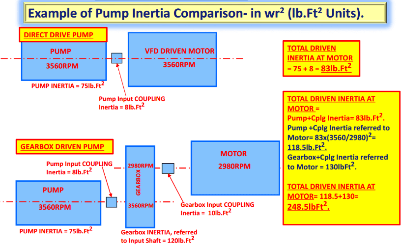
How Does a Gearbox Influence Inertia?
If a motor directly drives the pump, the values of the pump and pump-motor coupling inertias are the same regardless of pump speed. If the pump is driven by a gearbox and motor, however, the gearbox can have a major impact on inertia values. In this application inertia can be expressed as:
Pump & Coupling Inertia Totals x (Gearbox Ratio)2
A gearbox’s effect on inertia can be understood by analogy to a bicycle. When a bicycle is ridden at high speeds, the rider may change to a higher gear ratio (one greater than 1.0) to go faster. Such a ratio also requires the rider to put in more effort. Likewise, if a gearbox shifts to a higher gear ratio, the motor will have a higher load. The same logic applies if the gearbox is reducing the motor speed to drive the pump slower. When the gearbox ratio is less than 1.0, it will reduce the load requirements on the motor.
Here are some examples of inertia calculations:
PumpWorks Can Resolve Your Pump Dilemmas
Selecting the right pump and motor isn’t always simple. The torque curve represents how motor speed affects the output shaft, and understanding torque-speed characteristics is key to performance. Motors operate in a constant torque region at lower speeds and a constant power region at higher speeds, depending on applied voltage and given speed.
At PumpWorks, we help customers find the right pump and motor setup to match their needs. Whether you’re considering constant torque requirements or optimizing system efficiency, our experts can guide you. Contact PumpWorks online today for customized pump solutions.
Browse our available pump packages or contact a specialist today!